From CBCT Scan to Guided Implant Placement — The Complete Digital Workflow
A step-by-step walkthrough of a fully digital implant case: intraoral scan, CBCT, prosthetic-driven planning in CS 3D Imaging, SMOP surgical guide, guided drilling, and an immediate screw-retained temporary crown. This is the workflow every implant dentist wants to master.
 Dr Mathieu Rousset
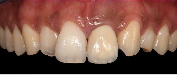
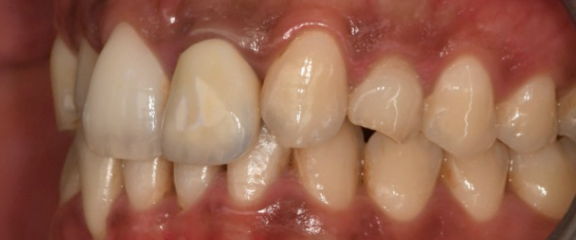
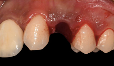
The patient presented with agenesis (congenital absence) of the upper left first premolar and the upper right lateral incisor. Previous orthodontic treatment had addressed the spacing, and the lateral incisor site had been left unrestored. Over time, the upper left canine (UL3) had drifted significantly into the wrong position.
The decision was made to extract the displaced UL3 and place an implant at the same site — an immediate placement following extraction. This type of case demands precision: the implant position has to be driven by the final prosthetic outcome, not just the available bone. Get the angle or position wrong by a couple of millimetres and the restoration either looks wrong, functions poorly, or both.
This case followed a fully digital pathway from diagnosis to surgery. Every step was connected — data flowed from one stage to the next without manual re-entry or guesswork.
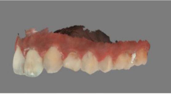
Step 1 — Digital impression. An intraoral scan captured the soft tissue anatomy and the existing dentition. This provides the prosthetic reference — showing the software exactly where the final crown needs to sit.
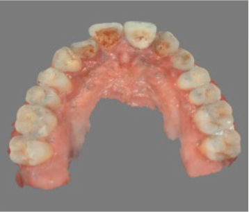
Step 2 — CBCT scan. A 3D volume was acquired using the Carestream CS 8100 3D. The CBCT confirmed root resorption on the UL3 (supporting the extraction decision) and provided the bone volume data needed for implant planning.
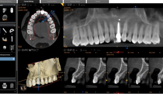
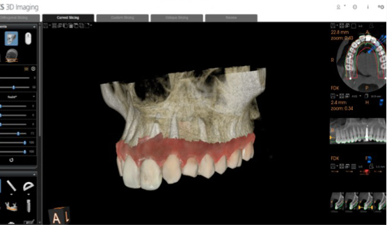
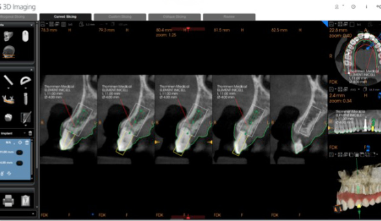
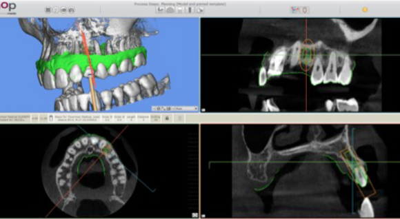
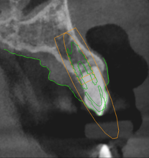
Step 3 — Prosthetic-driven implant planning. This is the key step. The CS 3D Imaging Prosthetic-Driven Implant Planning module automatically merged the CBCT volume with the intraoral scan — aligning hard tissue (bone) with soft tissue (gingiva and teeth) in a single view. The implant was then positioned using a crown-down approach: the ideal restoration position determined the implant axis, not the other way around.
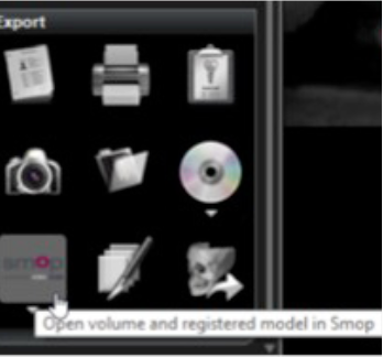
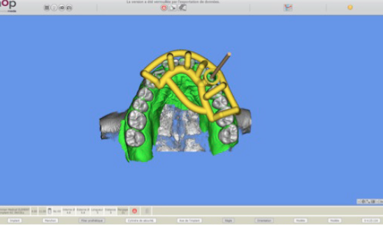
Step 4 — Transfer to SMOP and guide design. With a single click, the entire plan — 3D volume, digital impression, implant position, and references — transferred from CS 3D Imaging to SMOP guided surgery software. No need to reload data, manually align scans, or re-plan the implant position. The SMOP service centre designed the surgical guide and 3D-printed it, shipping it back with a Thommen Medical guided surgery sleeve.
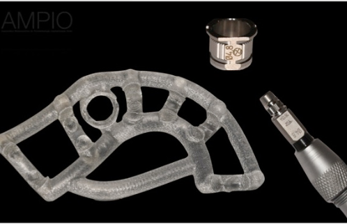
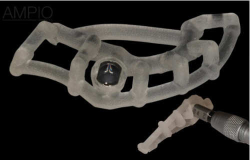
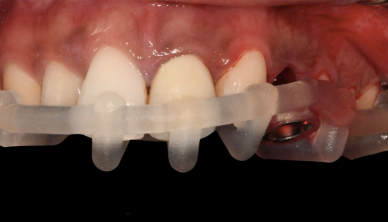
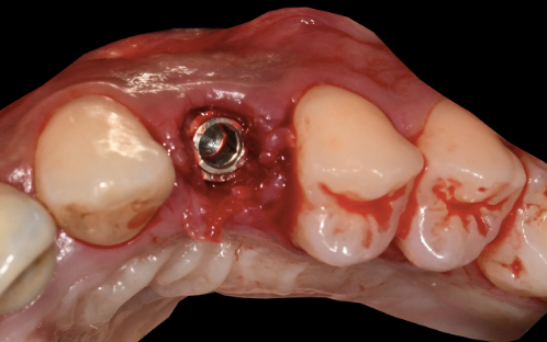
Step 5 — Guided drilling and implant placement. On the day of surgery, UL3 was extracted. The tooth-supported surgical guide was seated on the adjacent teeth and its fit verified. The SMOP guide design left the surgical site fully visible — giving the clinician direct sight of the osteotomy while still controlling the drill angle and depth.
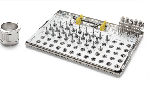
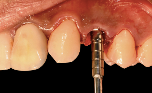
A Thommen ELEMENT RC implant (4.0 mm diameter, 11 mm length) with Inicell superhydrophilic surface was placed. The final 3D position matched the pre-operative plan exactly.
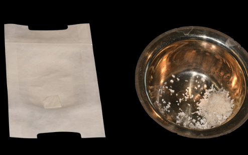
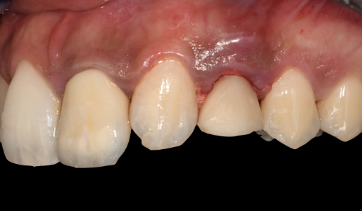
Step 6 — Immediate temporary restoration. A VARIOtemp abutment was placed, and a screw-retained temporary crown (designed by the lab in Dentalwings software and milled pre-operatively) was fitted immediately. A tunneling technique with a collagen membrane and porcine-origin hydroxyapatite was used to encourage bone regeneration and maintain the papillae.
The streamlined workflow between CS 3D Imaging and SMOP saved significant time. There was no need to reload data or manually re-align the scans — the planning transferred with a single click. That kind of integration is what makes guided surgery practical in everyday private practice, not just in university departments.
— Based on the clinical workflow of Dr Mathieu RoussetWant to learn this workflow hands-on?
We are running a guided implant surgery course in July 2026 at our Yorkshire education facility — covering prosthetic-driven planning, surgical guide design, and guided placement. Limited places available.
Register your interest →Prosthetic-driven planning puts the crown first. The implant position was determined by where the final restoration needed to be — not by where the bone happened to be easiest to drill. CS 3D Imaging's Prosthetic-Driven Planning module merges your CBCT and intraoral scan automatically, so you plan from the crown down in a single software environment.
One-click transfer to SMOP eliminates re-work. The biggest friction point in guided workflows has always been moving data between planning and guide software. The direct CS 3D Imaging → SMOP integration removes that entirely. No manual alignment, no re-planning, no risk of introducing errors between systems.
Guided surgery is not just for complex cases. This was a single-unit implant — not a full-arch reconstruction. The precision and predictability of a guided approach apply to every implant you place. If you are already taking CBCTs and intraoral scans, you are closer to guided surgery than you think.
CBCT interpretation is the foundation. Every guided workflow starts with a CBCT scan that someone has to read and interpret correctly. Our CBCT Level 2 Reporting Course builds the systematic interpretation skills you need before you can plan with confidence — covering bone assessment, anatomical landmarks, and structured reporting.
Carestream CS 8100 3D
Panoramic, cephalometric, and CBCT imaging in a single compact unit. The 75-micron high-resolution mode provided the bone volume data for prosthetic-driven implant planning.
View Carestream CBCT range →CS 3D Imaging Software
The Prosthetic-Driven Implant Planning module automatically merged the CBCT and intraoral scan, enabling crown-down implant positioning with one-click transfer to SMOP.
View CS 3D Imaging Premium →Ready to bring guided implant surgery into your practice?